01 / THE BODY
Keep the silhouette.
The white hood, doors and upper rear deck stay intact. Air enters through openings in the black bumper and side-skirt trim.
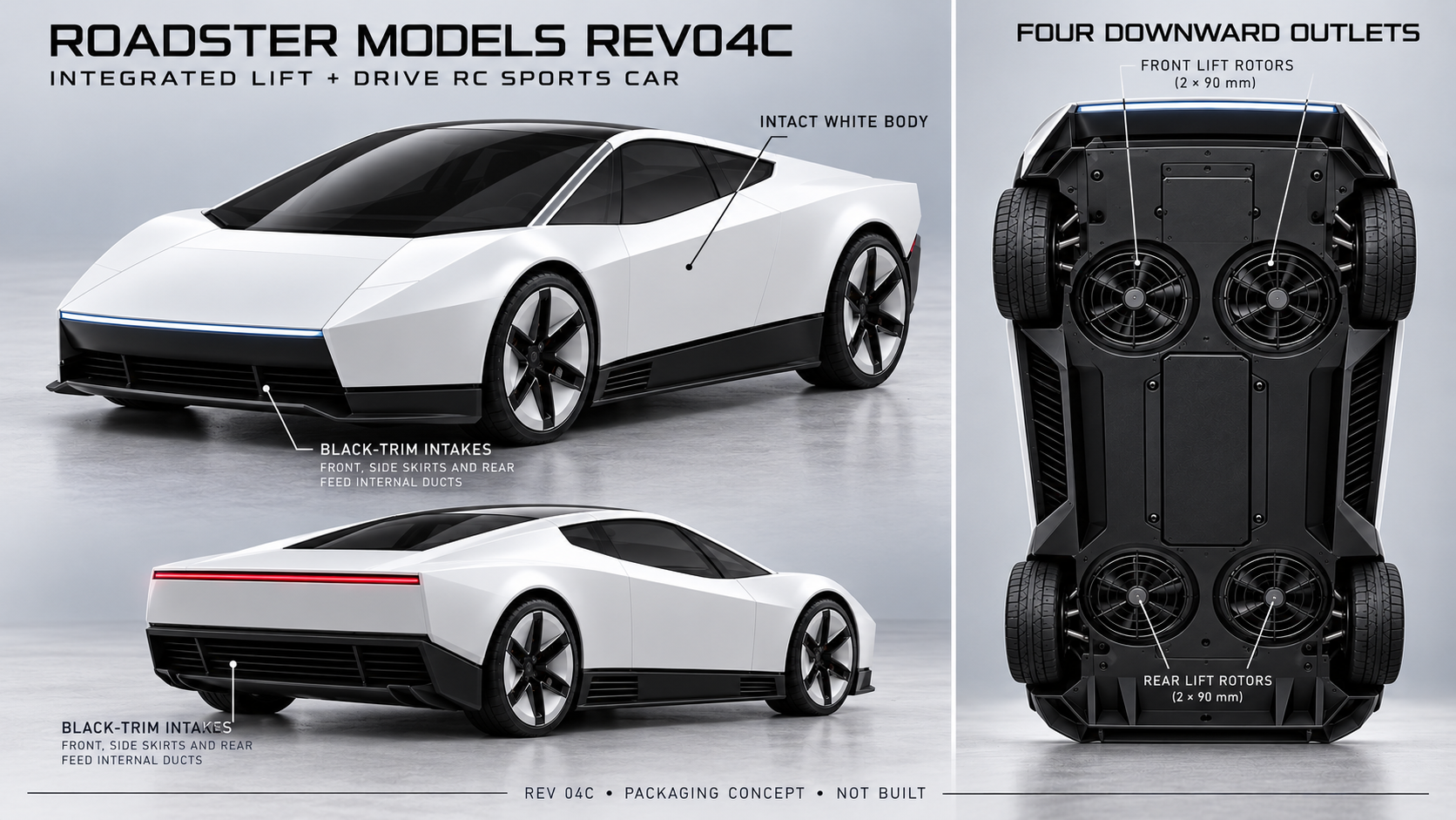
A complete upper body. Four recessed lift rotors underneath.
One fixed layout for road and hover development.
STAGE 01 · PACKAGING DESIGN · PHYSICAL LIFT TESTING NEXT
Scroll through the concept. All views describe the same proposed architecture.
The white hood, doors and upper rear deck stay intact. Air enters through openings in the black bumper and side-skirt trim.
Four fixed rotor modules are recessed under the car, two at the front and two at the rear. No external arms unfold. This graphic is a layout schematic, not manufacturing CAD.
Internal ducts turn the incoming air towards the lift rotors. Exhaust points downwards. The moving arrows illustrate direction only: flow rate, pressure loss and installed thrust remain unmeasured.
CONCEPT VISUALIZATION · NO VERIFIED HOVER · NOT A FLOW SIMULATION
Four fixed lift modules are recessed into the underbody. Air enters through grilles confined to the black lower front bumper, rear bumper and side skirts, turns through internal ducts and exits downwards. White hood, doors, fenders and upper rear deck remain uninterrupted.
The nose, canopy and rear deck have no exposed lift rotors. All visible inlet openings stay within black lower trim. Do not cut vents into white body panels.
Recessed modules need removable service panels, rotor retention, protected wiring and guarded outlets. A drawn grille is not proof of finger protection or debris resistance.
The battery, frame and wheel hardware must stay out of the inlet plenums and exhausts. Inlet free area, duct geometry and vertical motor clearance remain unresolved in CAD. Front/rear inlets must feed separate plenums above the lift rotors, isolated from hot downward exhaust.
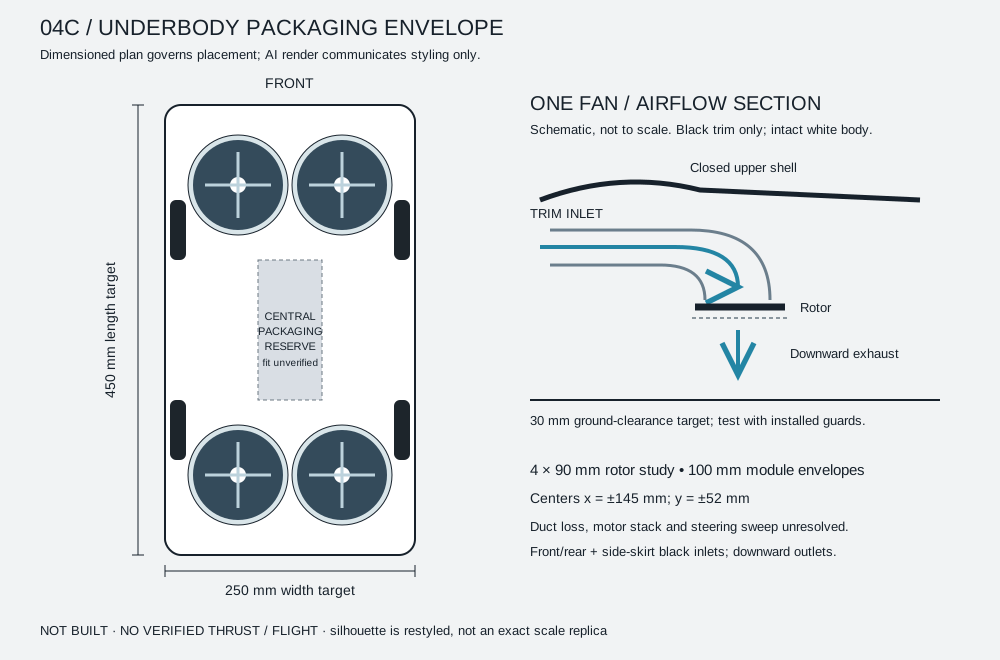
450 × 250 × 140 mm target. Compared with the prior 450 × 210 × 115 mm study, width increases 40 mm and height 25 mm. Actual packaging is not closed.
Four 90 mm rotor disks in 100 mm outer envelopes. Centers: x = ±145 mm, y = ±52 mm, measured from body center. Only 4 mm remains between same-row outer envelopes; structure and tolerances need review.
30 mm at the lowest fixed outlet guard is a study target, not a safe clearance rating. Check compression, surface debris, exhaust recirculation and takeoff behavior.
Wheel drive and steering. Lift rotors stopped during normal driving. The four underside outlets remain in place.
Stop the vehicle, neutralize ground drive and check the lift system. Rotors start only after arming checks; they do not appear or unfold.
All four underside rotors provide lift through downward exhaust. Wheel drive and any future rear boost stay disabled. 60 seconds remains a test objective.
There are no external arm-lock sensors in this architecture. Ground/flight output separation and controlled fault handling remain requirements, but the old arm-lock implementation is not accepted as the new safety design. An airborne fault must not automatically cut all lift.
Four 90 mm disks total about 0.02545 m², approximately 34.6% of four 153.07 mm disks. For equal thrust, smaller open rotors require more ideal induced power.
The proposed lateral moment arm is 52 mm rather than 215 mm, about 24% of the prior value at equal differential thrust. New inertia and control-authority checks are essential.
Black-trim grilles, bends, walls and outlet guards affect installed performance. Catalog free-air thrust cannot establish the output of a complete underbody module.
At an assumed 1.3 kg and air density 1.225 kg/m³, isolated open-rotor momentum theory gives approximately 182 W ideal induced power, about 1.70 times the old disk-size comparison. This calculation does not model the proposed ducts, motor losses, ground effects or actual electrical power. It cannot predict endurance.
The previous 1,220 g allocation + 80 g reserve is historical. New ducts, inlet guards, mounts and motors have no verified mass allocation. We do not claim this layout meets the ceiling.
4S 2,200 mAh is a reference candidate only. Motor voltage compatibility, pack dimensions, current, sag and cooling need new checks. Nominal capacity does not prove a 60-second hover.
Assembly 08 remains an optional ground-only requirement. It has no resolved package or mass allowance in this study and is not shown as installed. Decorative rear openings are not propulsion evidence.
All 45 historical IDs are preserved. External arm parts 04-01, 04-02, 04-03, 04-04 and 04-11 are retired from the current architecture, not renamed into ducts. Lift hardware must be reselected. New duct/plenum parts, cassette interfaces, black-trim inlet guards and outlet protection remain unassigned until the architecture is reviewed.
| ID | Historical identity | Rev 04C disposition |
|---|---|---|
| 01-01 | White body shell | Revalidate fit, mass and rating |
| 01-02 | Canopy & window insert | Revalidate fit, mass and rating |
| 01-03 | Shell posts & isolators | Revalidate fit, mass and rating |
| 01-04 | Front & rear light inserts | Revalidate fit, mass and rating |
| 01-05 | Interface covers & bumpers | Revalidate fit, mass and rating |
| 02-01 | Main rails / deck | Revalidate fit, mass and rating |
| 02-02 | Crossmembers & spacers | Revalidate fit, mass and rating |
| 02-03 | Battery tray & straps | Revalidate fit, mass and rating |
| 02-04 | Structural fasteners & inserts | Revalidate fit, mass and rating |
| 03-01 | Wheel hubs | Revalidate fit, mass and rating |
| 03-02 | Tires | Revalidate fit, mass and rating |
| 03-03 | Wheel bearings & axles | Revalidate fit, mass and rating |
| 03-04 | Front knuckles & links | Revalidate fit, mass and rating |
| 03-05 | Steering servo | Revalidate fit, mass and rating |
| 03-06 | Ground-drive motor | Revalidate fit, mass and rating |
| 03-07 | Ground-drive ESC | Revalidate fit, mass and rating |
| 03-08 | Rear reduction & differential | Revalidate fit, mass and rating |
| 04-01 | Rigid arm tubes | Retired from current architecture |
| 04-02 | Root mounts & clamps | Retired from current architecture |
| 04-03 | Mechanical retention pins | Retired from current architecture |
| 04-04 | Lock-state sensors | Retired from current architecture |
| 04-05 | Motor mounts | Reselect or redesign |
| 04-06 | Lift motors | Reselect or redesign |
| 04-07 | Lift ESCs | Reselect or redesign |
| 04-08 | Propellers | Reselect or redesign |
| 04-09 | Propeller retainers | Reselect or redesign |
| 04-10 | Guard rings & supports | Reselect or redesign |
| 04-11 | Arm electrical connectors | Retired from current architecture |
| 05-01 | Main battery pack | Reference only |
| 05-02 | Pack insulation & impact pads | Reference only |
| 06-01 | Flight controller | Revalidate fit, mass and rating |
| 06-02 | RC receiver & antennas | Revalidate fit, mass and rating |
| 06-03 | Downward optical-flow module | Revalidate fit, mass and rating |
| 06-04 | Downward rangefinder | Revalidate fit, mass and rating |
| 06-05 | Mode / ground controller | Revalidate fit, mass and rating |
| 06-06 | Electronics mounts | Revalidate fit, mass and rating |
| 07-01 | Distribution & current sensing | Revalidate fit, mass and rating |
| 07-02 | Regulated avionics supply | Revalidate fit, mass and rating |
| 07-03 | Branch wiring & connectors | Revalidate fit, mass and rating |
| 07-04 | Isolation / protection hardware | Revalidate fit, mass and rating |
| 07-05 | Signal harness & strain relief | Revalidate fit, mass and rating |
| 08-01 | Rear EDF assembly | Deferred / not packaged |
| 08-02 | Boost ESC | Deferred / not packaged |
| 08-03 | Inlet / outlet duct & mount | Deferred / not packaged |
| 08-04 | Inlet guard & retention | Deferred / not packaged |
Do not order the old lift system for this layout. No manufacturing-ready exploded drawing is released.
A planned experiment to measure the cost of routing air through the body. Test records will be added after physical measurements.
Establish the same motor, rotor, controller and outlet guard as a reference. Record thrust, loaded voltage, current, RPM and temperature.
Fit the inlet grille and curved duct. Compare at matched RPM, and separately at matched electrical power. Report installed thrust relative to the open-inlet reference.
Repeat at controlled ground clearances. Observe recirculation and the change in net vertical force. A single-module result must then be checked with all four modules operating.
Use the same calibrated rig and ambient conditions, repeat measurements, and report uncertainty. Log battery voltage sag and temperature throughout. No fixed duct-loss percentage or alternative takeoff weight is adopted before these measurements.
Installed thrust and power, complete assembly mass, inlet pressure loss, ground-clearance sensitivity and control response. Compare measured total lift with measured vehicle weight and the control margin required by the flight model.
90 mm describes the current rotor envelope, not a selected commercial EDF. Smaller rotors and heavier vehicles both change disk loading and power demand. Neither change is an automatic solution.
Every dimensional and performance value on this page is a design input unless explicitly labeled otherwise.