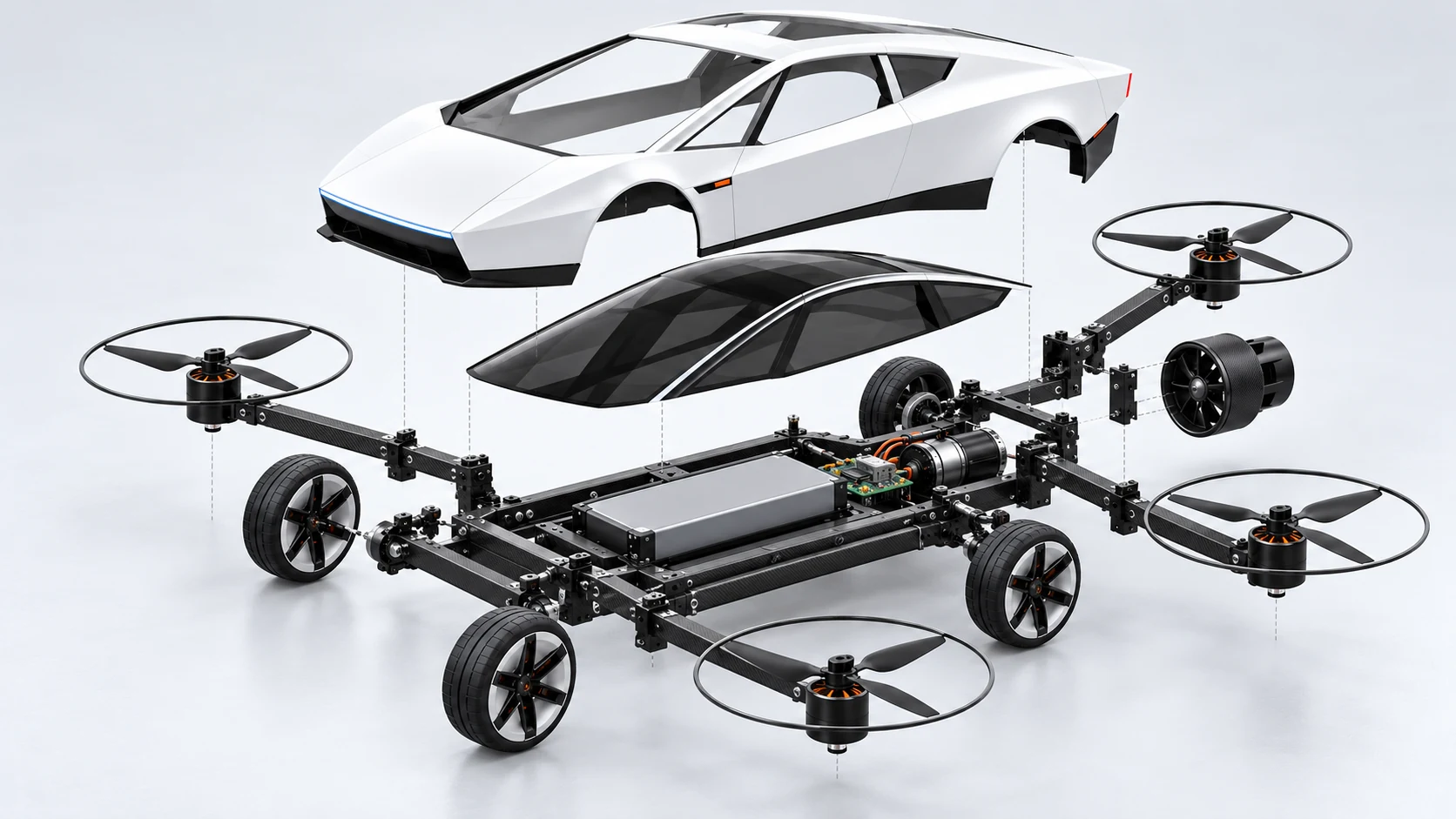
Polycarbonate shell
A thin formed shell carries the shape. Local ribs and mounts support it; rotor loads bypass the body panels.
A lightweight shell. A rigid core.
Every system has a job.
Explore how the photo-referenced body, ground drivetrain and removable lift modules could come together. This is a proposed architecture, ready for engineering review.
CONCEPT ONLY · NOT BUILT OR FLIGHT-TESTED · NOT A MANUFACTURING DRAWING
A thin formed shell carries the shape. Local ribs and mounts support it; rotor loads bypass the body panels.
A carbon frame and tubular arms aim to resist bending with less mass. Layup, joints and impact damage still need validation.
Nylon guards and local TPU bumpers can flex at contact points. Metal is reserved for joints that need it.
1.10–1.20 kg is a weight-reduction ambition. The current component budget remains 1.30 kg, including an 80 g contingency. No assembly has been weighed.
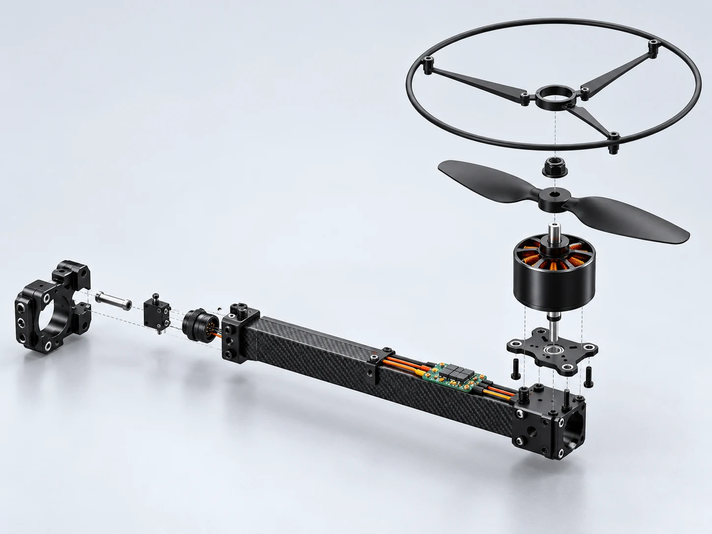
At the 1.30 kg design mass, each rotor supports an average 325 gf in hover. The proposed installed maximum-thrust gate is at least 650 gf per rotor at the minimum allowed working voltage.
These are calculated targets, not measured thrust. Guards, shell interference, temperature and the selected powertrain must be tested together.
Explore all 11 lift-module line items ↓Keep the eight assemblies, rigid removable arms, four lock sensors and rear ground-only fan. Improve the connections before adding mechanisms.
Download revision checklist ↗Avoid redundant plates, rails and spacers.
Mass: No savings claimed before an equal-load comparison and weighing.
Evidence required: Compare a single deck with local stiffening against minimal twin plates at equal torsion, bending and joint-load requirements.
Existing parts: 04-02
Reduce local crushing and fretting at arm roots.
Mass: External gross estimate: 6–10 g across four roots; reconcile with the existing arm allowance.
Evidence required: Define clamp torque; inspect tube damage and test slip under combined thrust, bending and motor torque.
Existing parts: 02-04
Reduce composite bearing damage around critical mounting holes.
Mass: External gross estimate: 4–6 g; do not count existing fasteners twice.
Evidence required: Check laminate damage after assembly and vibration tests. Define a preload measurement method; witness marks alone do not measure preload.
Make contact damage repairable without replacing the entire guard or shell.
Mass: External gross estimate: 12–18 g TOTAL across bumpers and guards, not per assembly.
Evidence required: Use unpowered impact specimens first. Specify mass, velocity, direction, fixture and blade-envelope clearance before setting pass limits.
Existing parts: 07-03 / 07-05 / 04-11
Protect wires at carbon edges and detachable connectors.
Mass: External gross estimate: 5–8 g; some protection is already budgeted.
Evidence required: Check insulation, continuity, connector retention and solder-joint strain after assembly cycles and representative vibration.
Existing parts: 04-03
Control retention-pin hole wear without adding unnecessary hardware.
Mass: External gross estimate: 6–12 g if adopted; not a committed addition.
Evidence required: Compare direct holes with bushed holes using matched loads and insertion cycles. Adopt only if wear or stiffness results justify the mass.
Four closed circuits do not prove four mechanically engaged pins.
Mass: Lock sensing already belongs to the baseline; additional fault-detection hardware is unweighed.
Evidence required: Test partial engagement, open/short circuits and stuck signals before arming. Define a separate airborne response; do not automatically cut lift power for a sensor anomaly.
Existing parts: 06-01 / 06-03 / 06-04 / 07-04
Localization and anti-spark behavior cannot be assumed.
Mass: Selection-dependent; no automatic upgrade to a heavier connector.
Evidence required: Test the selected firmware response to flow/range loss: attitude mode does not hold position. Measure inrush before choosing precharge; ordinary XT60 is not anti-spark.
The external 33–54 g gross estimate is unverified and overlaps existing allowances. No 120–180 g saving is claimed: folding hinges were already excluded. The 1,300 g budget is unchanged pending reconciliation and weighing. Existing images show the revision 02 architecture; revised joint geometry awaits CAD.
Tethered tests check controls and interlocks; they do not prove free hover. The 60-second milestone requires untethered hover in a protected test area followed by controlled landing. Log absolute temperatures and temperature rise against component limits; 60 seconds does not establish thermal equilibrium.
60 seconds is our prototype objective. The current software model completes it under nominal assumptions. Physical flight remains unverified.
These are scenario-specific software screens, not a reliability rating. Fault cases assess the response to the injected fault, rather than a full 60-second mission. Results were recorded on 20 October 2026.
1,300 g budget: 1,220 g allocated + 80 g reserve. A 1,100–1,200 g build is an aspiration, not a measured mass. Body envelope assumption: 450 × 210 × 115 mm.
4S 2,200 mAh LiPo baseline: 32.56 Wh nominal. The 70% usable-energy assumption gives 22.79 Wh. Four lift rotors on rigid detachable arms; installed thrust and battery sag still require measurement.
Assumed rotor centers: x = ±165 mm, y = ±215 mm. Guard outer diameter: 172 mm. These dimensions do not establish safe blade clearance or a finished CAD design.
Wheel drive and electric rear boost are ground-only. Both must be neutral before lift arming and throughout flight. No rocket propulsion is proposed.
Native ArduCopter 4.7.2 SITL loaded a custom 1.3 kg vehicle model with estimated inertia and a generic battery. Nominal run: 60.2 s hover, altitude 2.979–2.983 m, minimum modeled voltage 14.715 V. These precise numbers describe the simulation, not expected real-world accuracy.
Two hypothetical alternatives passed the software screen: lower resistance (0.05 Ω at 450 W reference hover power), or lower power (350 W at 0.08 Ω). Neither is a validated component configuration or a claim that the problem has been solved in hardware.
| Scenario | Result | Recorded hover |
|---|---|---|
| nominal | Passed software screen | 60.2 s |
| low thrust | Passed software screen | 60.2 s |
| high thrust | Passed software screen | 60.2 s |
| cg offset | Passed software screen | 60.3 s |
| high inertia | Passed software screen | 60.4 s |
| low inertia | Passed software screen | 60.2 s |
| high resistance | Not passed | 37.0 s |
| high power | Passed software screen | 60.4 s |
| heavy | Passed software screen | 60.2 s |
| slow motors | Passed software screen | 60.2 s |
| wind | Passed software screen | 60.2 s |
| gcs loss | Passed software screen | 14.5 s |
| gps loss | Passed software screen | 18.1 s |
| voltage collapse | Not passed | 12.2 s |
| combined adverse | Not passed | 0.0 s |
| resistance mitigation | Passed software screen | 60.2 s |
| power mitigation | Passed software screen | 60.3 s |
The latest six integration cases cover the normal mission, a ground lock fault, an airborne lock fault, supervisor object restart, stale-telemetry flag and combined health flags. All six passed their software checks. A separate suite passed 25 tests on Windows and 25 in Docker, including 20,000 seeded state-input steps per platform.
Ground lock faults inhibit arming. A sustained airborne lock signal fault requests landing without directly cutting lift. Simulated wheel/boost channels remain neutral in flight. These channels exert no ground-drive or boost forces in the flight model. Flight SITL ran natively on Windows; Docker ran the Python logic and audit tests.
There is no measured propulsion calibration, real thermal model, structural or collision validation, wheel/boost dynamics, physical lock verification or optical-flow acceptance. A sensor stuck high cannot prove the pin is mechanically engaged. Object restart and synthetic stale-data tests do not establish recovery from process death, a broken communications link or a physical power loss.
The selected motor’s published 16 V table starts at 511 gf, above the nominal 325 gf-per-rotor hover point. Extrapolation is not a measurement. Full-charge 16.8 V compatibility and conflicting propeller catalog dimensions remain open. Thrust and mass sweeps hold the reference power assumptions fixed; they do not predict real efficiency.
Download values are simulation outputs. No fabricated measurements have been entered into the prototype records. Revision 03 part IDs and Revision 02 concept illustrations remain unchanged pending CAD and bench validation.
Quantities are per vehicle. A “set” is a preliminary assembly; individual screws, bearings, wire lengths and fabrication dimensions await CAD and supplier selection. Materials are candidates, not purchase specifications.
45 component line items
No matching parts. Try a different term or reset the filters.
Keep the reveal-inspired silhouette. The shell carries appearance, not rotor loads.
Thin polycarbonate
Candidate: Thermoformed PC candidate
Lightweight exterior; thickness awaits forming and impact trials.
Candidate: Tinted thin PC
Glazing, with removable access to electronics.
Candidate: Nylon / elastomer
Support the shell without transferring lift loads into it.
Candidate: Lightweight lenses / LEDs
Appearance details; lighting and wiring mass included here.
Candidate: Nylon / local TPU
Cover removed-arm interfaces and absorb minor contact. Evaluate replaceable TPU pads jointly with 04-10; count their mass once.
Validate: Forming trials, weighed shell and mounting fatigue.
A light central frame carries the battery, wheel drive and four lift interfaces.
Carbon composite + local metal
Candidate: Carbon-fiber composite
Primary structure; laminate, thickness and rail sections TBD. Compare single deck with local stiffening versus minimal twin plates; select one. Specify laminate and fiber directions; 3K appearance is not strength evidence.
Candidate: Composite / aluminum candidate
Keep the frame stiff without a solid heavy floor. Avoid stacking redundant rails, decks and spacers.
Candidate: Light tray + textile retention
Hold the pack against motion without squeezing or puncturing it.
Candidate: Steel / aluminum as verified
Count and thread sizes follow joint testing, not this rendering. Evaluate local load-spreading washers; define preload verification separately from witness marks.
Validate: Bending, torsion, joint bearing loads and electrical isolation.
Rear-wheel drive and front steering keep the rolling system simple.
Light hubs + rubber tread
Candidate: Light polymer / composite candidate
Support tires with minimum rotating mass.
Candidate: Thin rubber
Grip and landing contact; compound and wall thickness TBD.
Candidate: Bearing steel
Four wheel positions; dimensions follow hub design.
Candidate: Tough polymer + metal pivots
Steer without contacting shell or lift interfaces.
Candidate: Commercial component TBD
Sized from measured steering load.
Candidate: Commercial component TBD
Rear drive; select using wheel diameter and torque requirement.
Candidate: Commercial component TBD
Reverse / brake behavior and supply voltage must match.
Candidate: Gear / shaft assembly TBD
Transmit wheel torque; verify weight before adopting a donor drivetrain.
Validate: Drive torque, brake distance, steering travel and installed temperature.
Four outboard modules provide lift. Rigid removable arms are the first prototype route.
Carbon arms + tough guards
Candidate: Carbon-fiber tube
Section and length require load and packaging checks.
Candidate: Local aluminum
Transfer rotor loads into the chassis; insulate dissimilar materials as needed. Evaluate clamp liners, defined tightening torque and combined-load slip/damage tests.
Candidate: Metal, specification TBD
Positive retention; not dependent on an electrical switch. Wear bushings remain conditional on comparative wear tests; no folding hinge in the first prototype.
Candidate: Switch / sensor TBD
Detect assembly state; open-circuit behavior must fail safely. Sense actual pin engagement; test partial engagement, open/short and stuck signals. Airborne faults require a separately validated response, not automatic motor cutoff.
Candidate: Composite / local aluminum
Carry thrust and motor reaction torque.
Candidate: Brushless motor TBD
Each must meet the installed thrust target with the chosen propeller.
Candidate: Commercial component TBD
Rated from measured current and thermal tests.
Candidate: Matched CW / CCW set
152 mm diameter baseline; blade count and pitch are not selected.
Candidate: Motor-matched hardware
Correct thread / retention method follows motor selection.
Candidate: Tough nylon candidate
172 mm outer-diameter placeholder; side guards are not complete contact protection. Evaluate replaceable TPU pads; share their mass allowance with 01-05. Impact criteria await defined fixtures and blade-envelope clearance.
Candidate: Keyed connector TBD
Current-rated connections, no structural load on connector bodies. Provide connector retention and strain relief for repeated removal.
Validate: Installed thrust, arm stiffness, retention, vibration and propeller clearance.
One pack supplies separate drive, lift, boost and regulated electronics branches.
High-rate LiPo candidate
Candidate: 4S 2200 mAh LiPo baseline
14.8 V nominal / 16.8 V full. Capacity and 250 g allowance require supplier verification.
Candidate: Electrical insulation / compliant pad
Protect the pack from carbon edges and local compression; included in battery allowance.
Validate: Actual mass, full-load voltage sag, cell balance, retention and temperature.
A mature multirotor controller stabilizes flight; a mode controller coordinates the ground system.
Commercial boards, selection pending
Candidate: ArduPilot-compatible candidate
IMU / barometer and suitable outputs; exact board not selected. Localization-loss response depends on selected firmware and operator capability; attitude control alone does not hold position.
Candidate: Radio hardware TBD
Clear link-loss signaling; carbon must not block antenna placement.
Candidate: Sensor TBD
Ground motion estimate depends on light and surface texture.
Candidate: Sensor TBD
Height measurement over the intended low-hover range.
Candidate: Controller TBD
Interlock wheel drive, boost and flight outputs.
Candidate: Isolators / light mounts
Mount boards and preserve sensor visibility.
Validate: Sensor field of view, vibration, firmware support, failsafes and mode interlocks.
Separate power branches keep the flight electronics stable when propulsion loads change.
Copper wiring + insulated electronics
Candidate: Power board / sensor TBD
Log current and energy; size for simultaneous worst-case loads.
Candidate: Regulator TBD
Stable controller power throughout the working battery range.
Candidate: Copper / insulated connectors
Wire gauge and connector ratings follow load tests. Protect carbon-edge crossings with appropriate grommets and abrasion protection.
Candidate: Rated hardware TBD
Maintenance isolation and appropriate branch protection. Measure inrush before specifying precharge. Ordinary XT60 is not anti-spark.
Candidate: Light harness
Route away from rotating parts and protect connections. Provide targeted grommets, abrasion sleeves and strain relief; reconcile existing allowance.
Validate: Peak current, brownouts, connector heat and branch protection.
A separate rear fan explores short ground-acceleration assistance. It stays off in flight.
Electric ducted fan
Candidate: Fan + motor, candidate TBD
Initial net thrust target 1.5–2.0 N, not a measured result.
Candidate: Commercial component TBD
Voltage, current and pulse duration follow testing.
Candidate: Light polymer / composite
Appearance outlets do not establish an effective flow path.
Candidate: Light guard / hardware
Validate pressure loss and rotor retention.
Validate: Net installed thrust, inlet losses, heating and boost-on / boost-off ground comparison.
The lift allowance includes 160 g for arms and retention, 220 g for propulsion and 60 g for guards. Fasteners and mounts belong to their assembly allowances. Tools, charger and radio transmitter are off-board and excluded.
Weigh parts, validate joints and measure installed thrust, voltage sag and temperature before flight.
Use a 4S 2200 mAh LiPo as the selection baseline. Disable wheel drive and boost during flight; verify loss-of-link and low-battery behavior.
Progress from short controlled tests to 60 seconds of stable hover per trial, followed by landing. Inspect, cool and recharge between trials as needed.
Plan for 60 seconds of stable hover plus a separate 30-second takeoff/landing allowance. This is an initial acceptance milestone, not a maximum-endurance claim. Flight tests require appropriate isolation and a qualified operator.
Remove the four lift modules and cover their interfaces. Preserve the body silhouette as closely as packaging permits.
Install and mechanically lock all four modules. The proposed footprint is approximately 50 × 60 cm around a 45 cm body. Lift hardware is visible.
CAD packaging, component selection and physical tests will determine what becomes a product.
Follow development ↗Back to the concept