How it works ·
Can the Tesla Roadster fly? Thrusters, suction and RC lift explained
The word “fan” can describe hardware doing very different jobs. Before comparing the new Roadster with a flying RC model, separate grip, acceleration and vertical support.
A suction fan is not automatically a lift fan
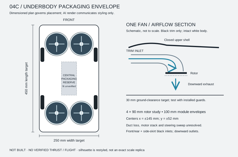
A fan installation can be arranged to reduce pressure under a car and increase the load on its tires. An underbody rotor intended for hovering instead needs the complete installation to produce net upward force. The direction and route of the airflow matter as much as the presence of spinning blades.
Reporting on the October Roadster event described both underside suction and separate thrusters. Our RC study must not treat that combination as evidence that its own four-rotor layout will hover. The event account gives the context.
Cold gas and electric rotors have different constraints
A cold-gas thruster releases stored pressurized gas. An electric rotor accelerates surrounding air using energy from a battery and motor. Both can generate force, but their hardware, energy storage and operating limits differ. Copying the appearance of an outlet does not copy the propulsion system behind it.
For our RC concept, the proposed solution is electric lift beneath the body. Rear electric boost is a separate ground-mode idea. We do not plan to use a compressed-gas stunt system as the basis for the current prototype. Tesla’s own feature and configuration details belong on Tesla’s product page.
Why a car-shaped shell complicates hovering
Rotor data measured in open air is only a reference for a rotor inside a car. A grille, a curved inlet and an outlet guard can alter the operating point. The whole installed assembly also adds weight. A useful comparison measures the same module in open-inlet, ducted and body-installed conditions.
Low ground clearance adds another variable. The floor can change the flow field, while neighboring modules can affect one another. A single fan held on a stand does not settle the four-module vehicle question. We need to record clearance and repeat the comparison, then investigate the complete arrangement.
What would count as convincing RC evidence?
Start with repeatable net-force measurements, matched operating conditions and uncertainty. Show the battery voltage under load rather than only its label. Record the motor, controller and battery temperatures over time, and weigh the complete module with its guard and duct.
Next, reconcile four installed modules with the complete vehicle mass, control response and center of gravity. Only then can protected vehicle tests address takeoff, stability and the initial 60-second hover milestone and, separately, a twenty-minute long-term research goal. A tethered check and a free hover answer different questions.
Follow the experiment
Our three-stage comparison plan describes the planned measurements. The blank test record is available to download. It contains no completed test results. If you want to follow the evidence as it develops, choose “Hover development” in the interest form.
Sources & scope
Sources reviewed on 22 October 2026. External reporting, documentation and manufacturer statements are attributed. RC calculations and design discussion are explanatory; they do not establish our vehicle’s flight performance.