Airflow & rotors ·
Ducted fan vs open propeller for an RC hover car
A ring around a rotor might be a protective guard, an aerodynamic duct or both. Its appearance does not establish how much useful lift the complete vehicle will produce.
Guard, duct and EDF are different descriptions
A guard is intended to keep objects away from the blade path. An aerodynamic duct is shaped as part of the propulsion system and can carry forces itself. EDF commonly refers to an electric ducted-fan assembly, but a diameter label does not specify its mass, intended operating point or hover efficiency.
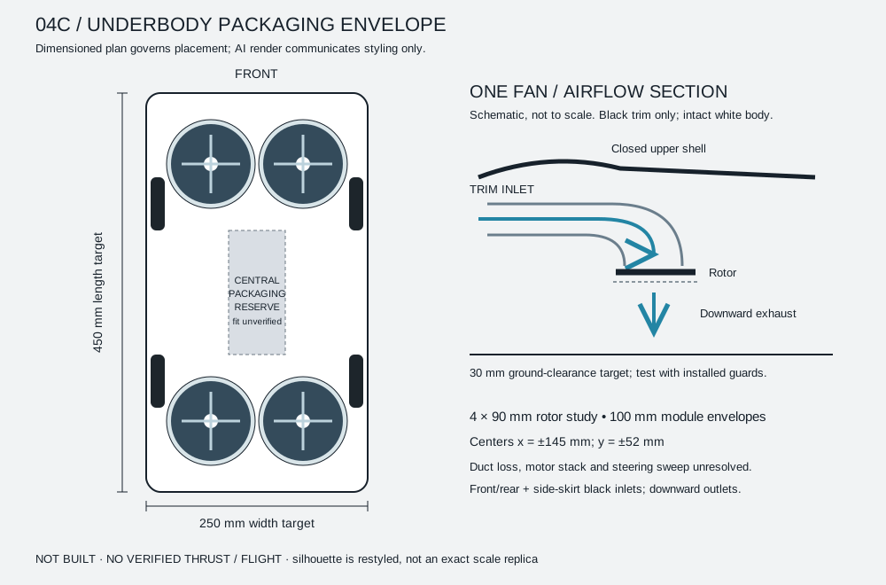
Our study's 90 mm rotor envelope is a packaging input, not a selected commercial 90 mm jet-model EDF. Substituting a catalogue assembly requires checking its complete dimensions, weight, electrical requirements and measured force in the intended orientation.
There is no universal percentage advantage
A duct can change the pressure field and total thrust, while its inlet shape, clearance, supports and guards also influence losses and weight. An open propeller needs its own installation space and protection. Compare the complete systems rather than assuming that either one always wins.
A 2022 experimental and numerical study compared symmetric and asymmetric duct shapes for a particular VTOL design and found different hover performance. It is evidence that geometry matters. Its numerical results should not be transferred to our much smaller, differently installed module as if they were measured here.
What the car body changes
An isolated duct can have unobstructed inlet access. Our concept instead routes air through black lower trim before exhausting downward. Grille area, the bend, internal obstructions and proximity to the ground all need attention. The complete shell may change the module's flow environment.
What matters to the vehicle is the net vertical force of the installed system at an acceptable electrical and thermal load. Looking only at rotor thrust can miss forces on the body and duct. An attractive airflow animation cannot quantify those forces.
A practical comparison matrix
Keep the motor, rotor and controller settings consistent. Measure an open-inlet reference with its outlet guard, then add the proposed grille and duct, then the surrounding body section. Record force, loaded voltage, current, RPM, temperatures and installed mass for each arrangement.
Make matched-RPM and matched-electrical-power comparisons separately. Repeat test points and preserve the raw logs and measurement uncertainty. If a test is stopped because of vibration or heat, retain that result rather than reporting only the favorable run.
Protection must also be measured
A guard takes space and mass and may deflect under load. Blade clearance and retention need a mechanical review in addition to an airflow review. A surrounding ring does not make a spinning rotor harmless or establish suitability for use near people.
Our installed-module test plan describes the next comparisons. The intact-body architecture remains fixed for the current research direction, while the twenty-minute objective remains unproven. If you want to follow this work, select engineering or hover development in the interest form.
Sources & scope
Sources reviewed on 22 October 2026. External reporting, documentation and manufacturer statements are attributed. RC calculations and design discussion are explanatory; they do not establish our vehicle’s flight performance.